drawing doctor
Turn messy customer drawings into cut-ready parts
Prepare CAD drawings for quoting and production by resolving common issues and identifying the parts customers actually want.

Spend less time cleaning drawings

Reduce risk of quoting the wrong parts

Move from drawing to quote to cut with fewer manual steps


.avif)
Reduce delays caused by messy customer drawings
Before
Manually cleaning CAD files just to prepare a quote
Quoting extra views, borders, or the wrong parts by mistake
Missing hidden issues like double lines or broken geometry
Losing time clarifying drawings before you can even price the job
Cleaning drawings at multiple points in your production process
After
Clean, quote-ready CAD drawings
Clear identification of the parts to be cut
Common drawing issues flagged early
Faster, more consistent quoting across your team
Save time in production by only cleaning drawings once

The easiest way to prepare drawings
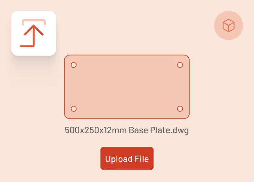
Upload
Upload your customer’s CAD drawings in seconds.
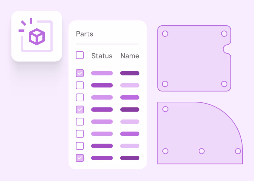
Identify
Drawing Doctor highlights common issues that can block quoting or production, helping you understand what needs attention.
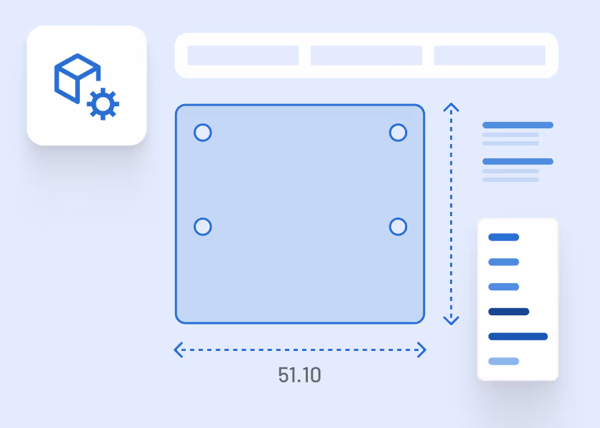
Correct
Remove or ignore unnecessary geometry and separate individual parts so you can focus on what actually needs to be cut.

Quote
Use clean, focused parts to generate more accurate quotes and export corrected files for production if needed.

Everything you need to clean drawings for quoting and production
From upload to quote-ready parts, Drawing Doctor helps reduce manual cleanup and avoid costly mistakes before pricing begins.

Issue detection
Highlights common problems like double lines, small gaps, and hidden geometry that can affect quoting and cutting.

Part identification
Separate individual parts from multi-part drawings and remove title blocks, borders, and side views.

Quote-ready output
Use cleaned geometry for accurate pricing and export corrected drawings for production workflows.


Save time, reduce errors, and quote with confidence
Drawing Doctor helps turn messy customer drawings into clear, quote-ready inputs.

Spend less time fixing drawings before pricing

Quote exactly the parts your customer wants made

Keep quoting moving, even with imperfect files
Why fabricators use Drawing Doctor
"Having all the right measurements reduces the risk of errors. It makes a big difference knowing the information going to the shop floor is correct and complete."

Derek H.
President
,
Hammer MetalWerks
“Tempus Tools saves me hours of time a month on my quoting and it’s very easy to use, even for someone like me that isn’t a tech geek. It enables me to accurately quote for my own parts I laser cut and take out the guesswork.”
James S.
,
Shug Laser Cutting
“Since implementing Tempus Tools, we’ve found it is much more accurate, reliable, and fast. Instead of two people quoting full time, we can now have one person do a better job in a quarter of the time.”
Olivier Samson
Vice President
,
MSG Industries
“I like that my laser machine operator and I can get an accurate idea of material usage, time, labour, and other relevant data for each job – and it greatly reduces the risk of human error, because Tempus Tools is a rules-based program.”
Frank M.
Owner
,
Rolleston Sheetmetal
Ready to prepare drawings without slowing down quoting?
Clean up customer drawings, identify the right parts, and move into pricing with confidence, all inside Tempus Tools.
Cleaner drawings before quoting
Fewer mistakes and less rework
Faster quotes, more consistent results